WELCOME
TO THE WORLD
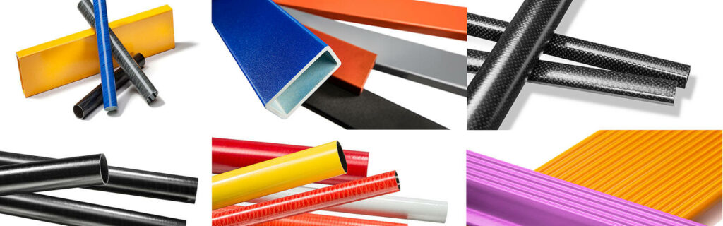
OF PULTRUSION
ABOUT EPTA ?
EPTA – The European Pultrusion Technology Association was created in 1989 by the leading Pultruders in Europe with the mission to support the growth of the composite profiles industry by maximizing external communication efforts and having an actively contributing membership.
Pultrusion is one of the longest established technologies for manufacturing profiles made from fibre reinforced plastics. The aim of the Association was, and remains, to reinforce the position of this process technology and promote their common interests. Today, the European Association of Pultruders has over 30 members throughout Europe and provides a strong network for pultruders sharing know-how and marketing ideas they have developed jointly…
AGENDA
- JEC World 2024 (official partner WPC) – Paris, 5-7 March 2024
 Paris
Paris - EPTA Board Meeting
 The next EPTA board meeting will take place at July,… Continue reading EPTA Board Meeting
THE PULTRUSION PROCESS